This is a quick demo using a feature of PCMCIA, allowing low quality audio to be fed directly to the computers PC Speaker. This was intended for modems to be able to output sound for dialing and connecting but there are a few soundcards that had this ability.
In the following list you can see some cards with the note “Outputs to PC Speaker). Soundcard List – GoogleSheet
The quality will vary between systems depending on how they implemented the internal audio. We will be able to use the EQ on the DSP to try and further optimize the output to get the best possible quality between systems.
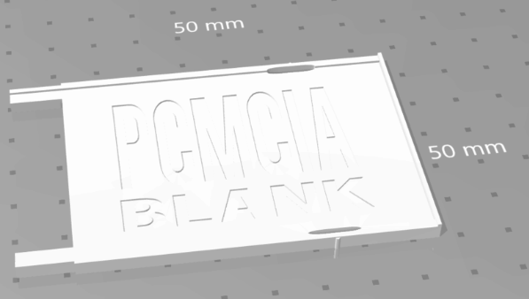
Here is the initial breakout board. It got a bit bigger than I had planned, but I wanted to get every function included out of the box. You can then make your own cables specialized to specific uses if you want something compact.
I also would like to modify this 3d print so that it extends out further, and it could be used in the slot below (where available) to support the breakout board and prevent it bending down.
I still plan to make some specific use cables i.e. audio only, and you can still make your own cables very easy as the connectors are stocked everywhere.
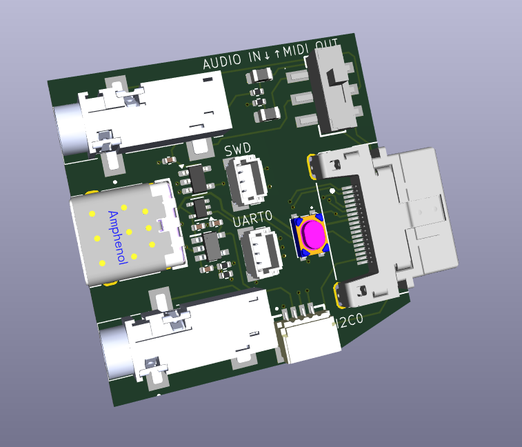
Breakout Board V1
3.5mm amplified headphone output
3.5mm type-a midi output or audio line-in for mixing in dsp.
USB-C connector (USB 1.1 from RP2354) for Programming or OTG cable with mouse or gamepad/joystick.
There are several ways to use the PicoPCMCIA for networking and I will go into detail on this in another update, but here I want to focus on something new I added, a basic onboard router.
The Issue
The PicoPCMCIA emulates an NE2000 network adapter, giving it near-universal support. Almost any device with a PCMCIA socket that supports networking already has NE2000 drivers available. The tradeoff is that the host sees it as a wired connection and has no awareness of Wi-Fi settings like SSID or key. To configure wireless, you must either use a custom utility on the target system or manually edit a configuration file on the SD card.
An excellent example of such a custom utility for a similiar scenerio (BlueSCSI DynaPort), is the “BlueSCSI Desk Accessory” written by Joshua Stein.
I hope to (or somebody will) adapt this to work with the PicoPCMCIA card for use with Macs, but that leaves many other platforms so for day 1 I needed a more universal solution beyond the DOS utility I will include.
The “Solution”
I’ve added a rudimentary onboard router to the PicoPCMCIA card.
On power-up, it automatically (if enabled) attempts to reconnect to the last used SSID. The host system (your PC/PDA) is always assigned a fixed IP address of 192.168.1.100, even if Wi-Fi has not yet connected. This is especially useful for operating systems without DHCP support, as the address can be statically configured.
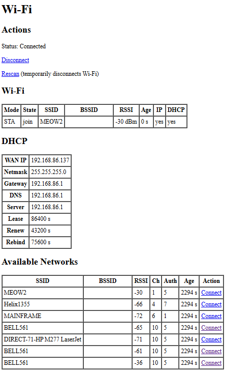
A simple management interface is available at h t t p://192.168.1.1/wifi. It uses a very basic HTML page designed to work with virtually any web browser. From there you can view the connection status, see what networks are available and attempt to connect. As this is the Pico doing the connection this of course can be any 802.11/b/g/n 2.4GHz network WPA/WPA2/WPA3 regardless what your computer/os is aware of.
Once Wi-Fi is connected, the host has IP network access through NAT routing, and WAN status is displayed on the management page. NAT also allows simultaneous use of Wi-Fi by both the host and the Pico itself, enabling additional features such as time synchronization or outbound connections from the emulated modem.
One point I would like to address is a way for devices using very simple browsers to be able to navigate through potential captive portals on public wi-fi’s. This will require some offloading of SSL etc. For another day.
Current Interface
This is simple HTML and can be improved easily, this is the bare minimum to get things going.
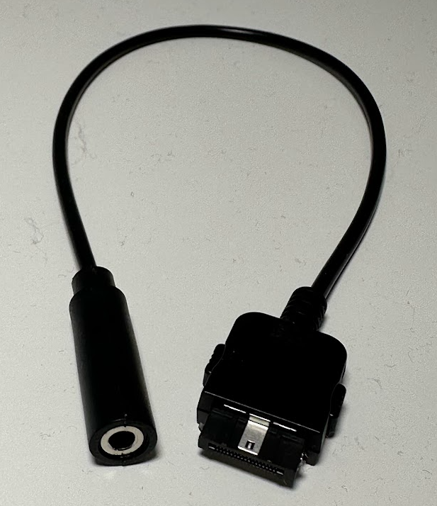
I selected the 18pin HRS connector as in the end it was the best way to get as many signals out of the card in such a small space, as we need the rest of the card edge for the SDCard and Antenna.
I had planned to include various cables with each card, but reality set in once I got quotes on custom cable assembly in low volumes.
I will provide some cable choices as options for an added cost. I will also offer the unsoldered connectors for those who wish to make their own cables, I will buy a bunch at once so it will be a bit cheaper than you buying your own from Digi-Key/Mouser and will save on shipping.
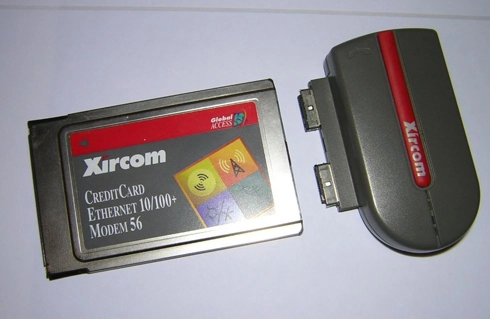
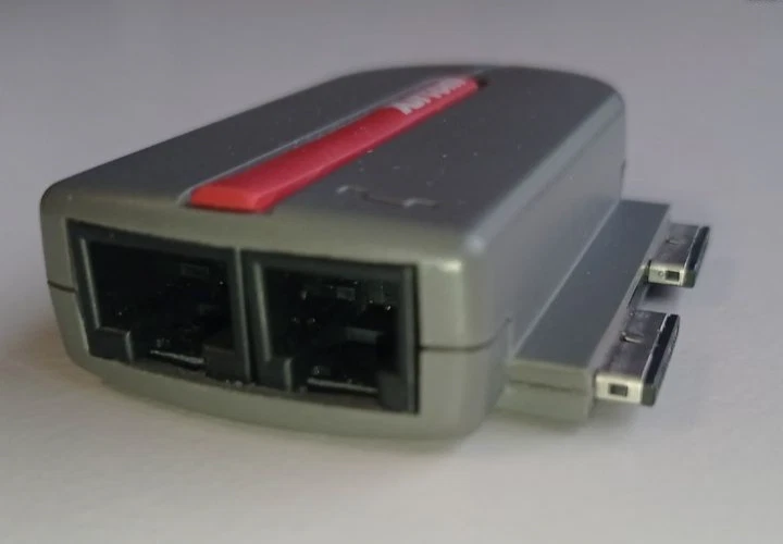
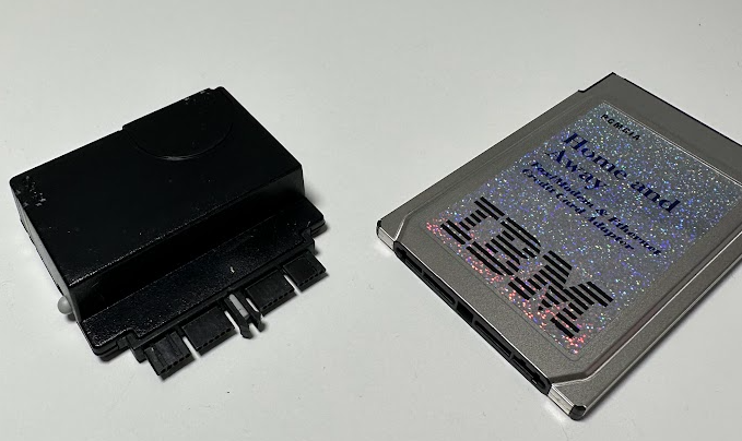
While contemplating this cost issue Kaede mentioned interest in making a PCB breakout board for development and it reminded me of these IBM/Xircom “rigid” dongles, which is the answer to the problem. A simple breakout board can be assembled much cheaper than a hand soldered cable and can provide all the basic features needed.
I’ve placed the Breakout into its own repository and I am working out the final details on it. Any feedback on features you would like to be included on this breakout would be appreciated.
Limitations / Constraints
Must not be wider that 14mm from the center of the connector on the right hand side to ensure it can fit onto cards in some confined spaces.
Can go wider on the left side but will obstruct the MicroSD. This should be okay as it is not intended to be hot swap.
Want to keep the size as small as possible for convenience but also to minimize leverage and damaging the connector.
Planned Connections
USB-C (For programming and OTG peripherals)
BOOTSEL Button (For programming)
3.5mm Headphone Jack (Amplified)
3pin JST-SH for RP2354 SWD
2.5mm MIDI OUT (not added yet)
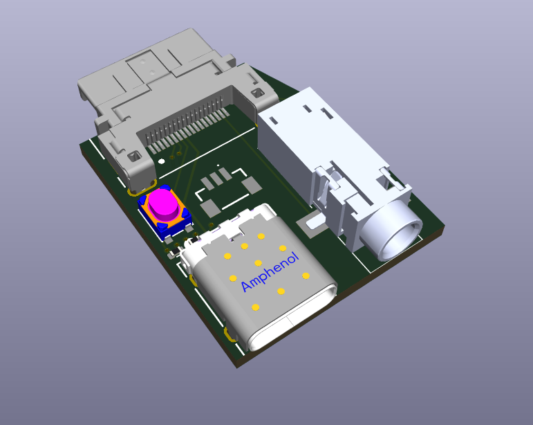
If the budget can permit, a 3D printed clamshell to give it a finished look will be nice.
Example Rendering
Current Pinout
Pinout
Pin
Signal
Notes
1
SWCLK
RP2354 Serial Wire Debug (SWD)
2
SWDIO
RP2354 Serial Wire Debug (SWD)
3
GPIO34
User I/O: GPIO, UART0 TX, or I²C1 SDA
4
GPIO35
User I/O: GPIO, UART0 RX, or I²C1 SCL
5
USB D−
RP2354 USB Port
6
USB D+
RP2354 USB Port
7
BOOTSEL
Boot select (firmware flashing / recovery)
8
5V
5 V from PC bus (350 mA fused)
9
GND
Ground
10
I2C0 SDA
I²C master (onboard DSP + external peripherals)
11
I2C0 SCL
I²C master (onboard DSP + external peripherals)
12
—
Not connected (Yet)
13
GPIO26
UART1 TX (also internally connected to SAM2695 MIDI RX)
14
IN1_L
Line-in left (to DSP)
15
IN1_R
Line-in right (to DSP)
16
HPL
Headphones out left (from DSP)
17
HPR
Headphones out right (from DSP)
18
GND
Ground
Connectors
The PicoPCMCIA External I/O uses Hirose ST-series connectors, chosen for their compact size and robust locking mechanism.
I have been slow to update the website but progress has been ongoing on the Pico PCMCIA project and I am now very close to producing the card. Much more compatibility testing has been done (I have been posting videos on youtube), and additional features have been implemented such as the CD-ROM emulation.
My fascination with PCMCIA cards was created out of “necessity”. Most of my retro computing interest revolves around networking, and I wanted something that could natively attach to modern Wifi networks without the need to maintain an old linksys router just for my retro computers. There are many ways to do this, I just wanted something as clean and compact as possible. I was also left out of being able to use the various ESP based wifi modems as I mainly use an IBM PC110 and it has no serial port without a dock.
At the start I looked at butchering existing ethernet cards and wiring in a wifi232 module coupling together the ethernet PHYs. This was very sketchy and the module was large, no real hope of scaling it down.
I quickly moved onto attempting to make my own entire card. I used a small GAL for some address decoding, a parallel UART chip and a flash chip along side the esp8266. This worked quite well and depending on the crystal selected, when having the divisor at 0 (usually 115200 baud) it would actually be 460800. It was quite feasible to fit this onto a board in a tiny case, but the speed limitations and it only being a serial interface always had me thinking about an ethernet interface instead of or in addition to the UART. I did play with SLIP and various ways to use the serial interface to get onto the LAN, but it was not fast enough or transparent enough for what I wanted.
I came back to trying to emulate an NE2000 card on the ESP8266 (also tried ESP32). It was just too slow though, the interrupt latency on the ESP was already almost my entire 12uS time limit for an I/O cycle, and because of the limited IO on the all the ESP’s I needed to use an I/O expander chip or external multiplexer, and in both cases it was just so slow there was no chance. I even played with using a dual-port sram to act as a place to store the CIS on boot and to simulate the registers but there was just no overcoming how slow the ESP was in handling interrupts and manipulating the external multiplexer or expander. Maybe there were some other approaches but I put this back on to the back burner.
Then I saw the work by Ian Scott on the PicoGUS that was using a Rasberry Pi Pico to talk to an ISA bus. This brought the Pico to my attention and I quickly connected one to the PCMCIA bus to play around. I quickly saw that the interrupt latency for the PIO was very low, and the PIO itself allowed some very fast and easy coordination of the I/O wait signals and other potential multiplexing and that is how I arrived where I am at now.
It is a very simple design. I use a CPLD to handle some of the “glue logic”, and to deal with the multiplexing, and it has the added benefit of having 3.3V I/O which is compatible with the Pico, but the I/O is also 5V tolerant which is compatible with the PCMCIA bus.
Next steps, I would like to encapsulate it into a card much like the legacy wifi cards. There will be some bonus functionality available through the USB port operating in host mode.
And depending on mechanical limitations perhaps an audio jack. That may get left to a larger version of the card with more functionality in the future. With the Pico there are so many possibilities.
I am a few months late updating my website on this. I designed a prototype board and assembled a prototype board and completed the switchover to a CPLD. Current status I partnered with somebody that specializes in this kind of thing to complete the analog audio design and sort out various details to make it manufacturable. I hope to have more updates on this soon. Below is a video demonstrating the DMA emulation in action, protected mode games and all.
I have not posted anything about this recently, this is one of the other projects I have been playing with. The goal is to create a PCMCIA soundcard that has the following featureset:
Yamaha OPL3 on the expected 388h address (this is done and working)
MPU-401 with full intelligent mode on the expected 330h (this is done and working)
Onboard Dream.fr wavetable general midi chip connected to the output of the MPU-401 (tested and working)
Option to disable onboard wavetable and only use external midi dongle
Gameport on the expected 200h – 207h (working but needs to be optional to enable/disable).
Digital audio via fully soundblaster compatible interface.
There are very few cards that ever existed that provided SoundBlaster support (IBM 3D Sound PCMCIA), and they are near impossible to find for purchase, so it lead me down the path to make one.
The learning curve has been steep as this project covers multiple areas all of which I was unfamiliar with at the start (and am now slightly familiar with). I got a general proof of concept working pretty quickly but spent too much time playing with wav files and large transfers (i.e. sbdiag tada.wav).
My recent reworking of how I was hooking interrupts solved some other issues I was having with protected mode games so I started to do some better testing on Doom,Duke3D etc and this is when I came to realize that they only use 4k or smaller buffers and the actual transfers are 128 bytes or 256 bytes per autoinit cycle. This totally makes sense given the realtime nature of sound effects during unpredictable gameplay.
I currently refill the 4K DSP every time it drops below half-full. This is not going to work. So I need to think about a better way to handle this.
I was avoiding modifying the DSP code, but for no good reason really. I think it is time I modify the DSP code so that my TSR can have complete visibility into how many bytes are being expected during autoinit mode. I am going to think about it a bit.
I am still alive and working on the project, mainly I have been messing around with this idea for the keyboard light, and generally just trying to optimize the 3D model for the bezel.
Something I have noticed is that I can hear a slight buzz from the onboard speaker and headphones when volume is turned up to full and no sound is playing which is most likely originating from the DC-DC converters. I am going to look into that some more and try to cancel that out with some better filtering on the power supply side of things. It seems that even an unmodified PC110 has this noise when the volume is turned all the way up, even with no inverter connected at all.
The BIOS patch is about ready, it works properly I have just been working on proper safeguards (making sure on a/c power and battery is charged etc).
Here is the current revision of the board. I was not paying attention and I ran those traces too close to that mounting hole, not a major issue as the screw goes into plastic and is not tight enough to damage the solder mask, but still not proper I will move it. DC-DC converts of course are on the back as seen in some other photos.
Here is the keyboard light in action, on one of them is working as I broke the other one and I was lazy to deal with it. Maybe only one LED is needed (if any really).
And here is the 3D printed bezel poorly painted just to see if it would block the light (it does). Feels strange without the IBM logo.
And here are just some random pictures working of 3D model progress.
As is customary with all my hobby projects, completion is illegal, so I look for improvements and additions.
Unable to fall asleep, I decided to take a break from scrolling twitter and play on the PC110. This is when I realized, of course, the keyboard is not illuminated and I could not type. So I wondered, can I integrate a light onto the lid as I have had on previous thinkpads.
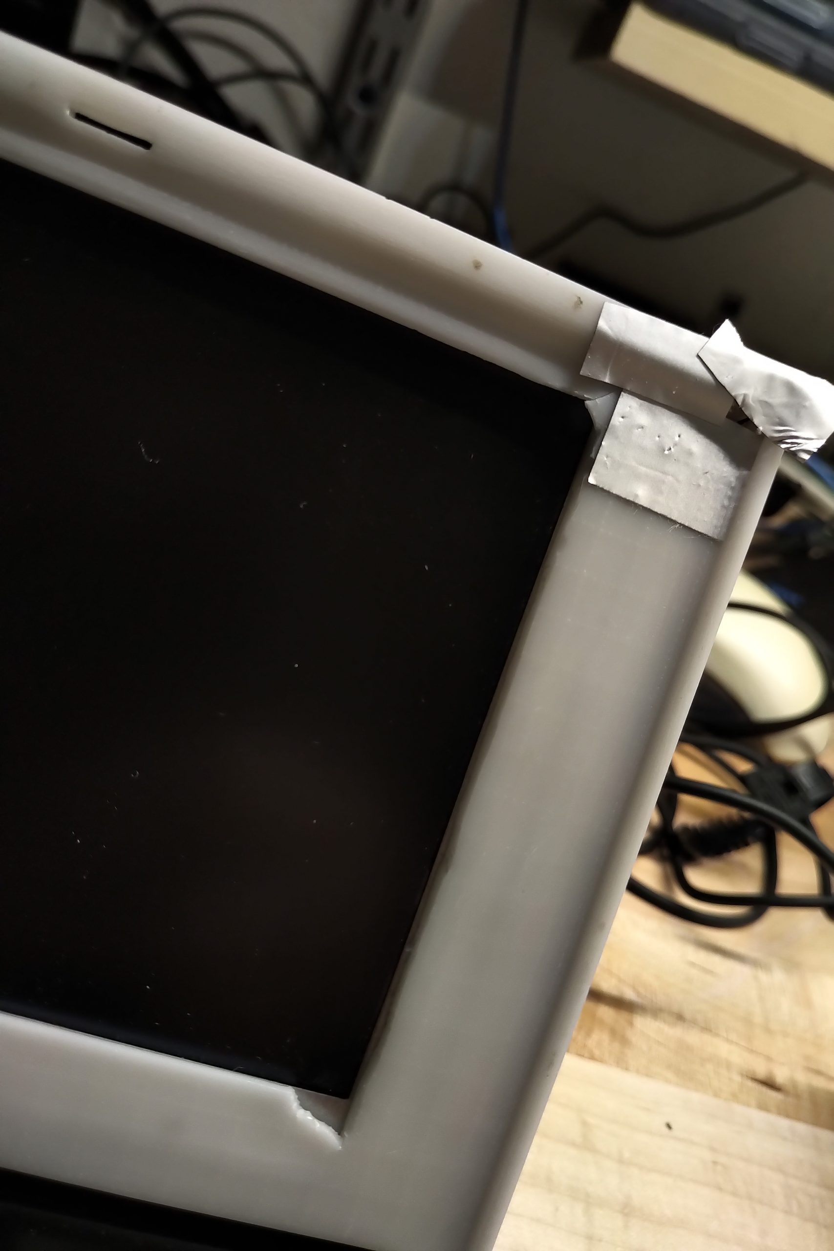
The screen actually looks good. You can see the uneven backlight because I have it turned up quite high, showing an all black screen, in a dark room.
I have the shielding tape because the unpainted plastic was getting illuminated by the light as well from behind. If I move ahead with this, it will most likely have to go on the corner as space is very tight in the middle due to the latch.
I played with placing it other places further down near the keyboard, and while that can work it it would be difficult to conceal.
As I mentioned in my video, it is currently blue as I burned out the only white 0603 LED I had on hand, but I lots of red and blue from a previous project.
I will also thing is a nicer way to control the brightness of the display and toggle of the keyboard light, make sure i am making the best use of the limited options.