This is just a quick update. This is more a journal to myself and as always I most say I do not know what I doing generally, so consider this as entertainment more than information.
TLDR: I have had some success using the Hitachi level converters and terminating capacitors. I believe this issue is all about transmission line theory, which I am aware of but do not understand so this is trial and error. I am ordering another revision of the board this week and starting to try and finalize the 3D model for the bezel.
I do still notice a blue tint in certain mode tests, I am not certain this is a hardware issue yet I need to investigate it more once these other issues are sorted out.
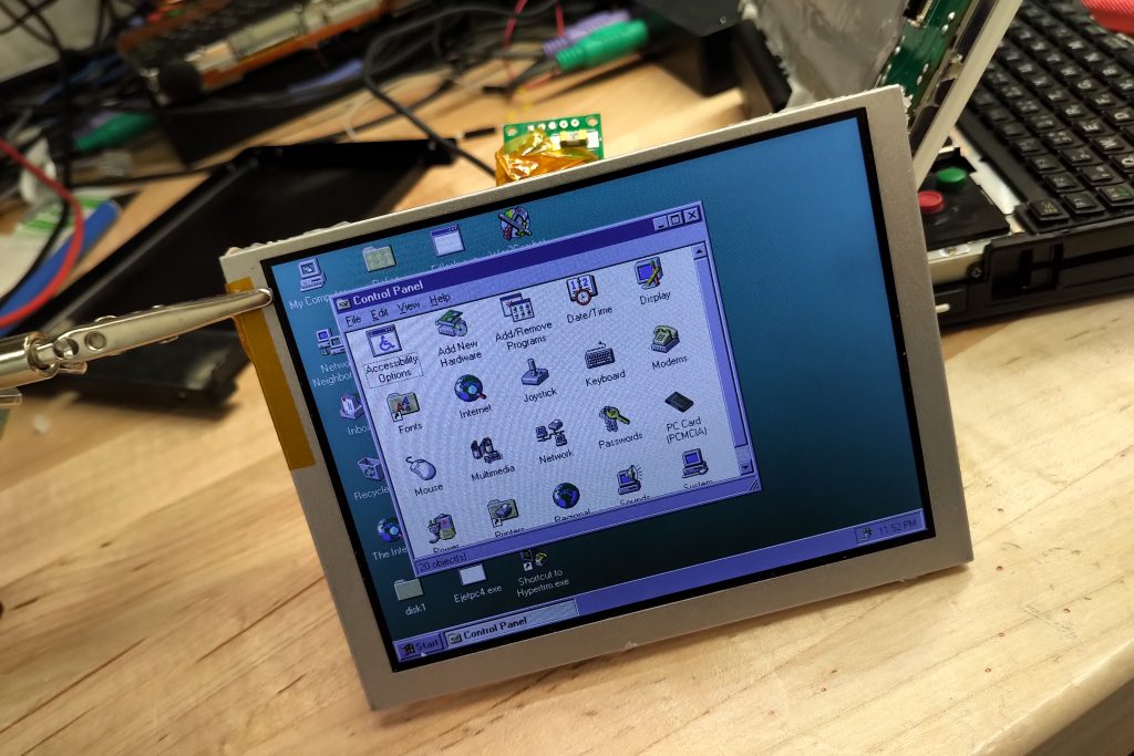
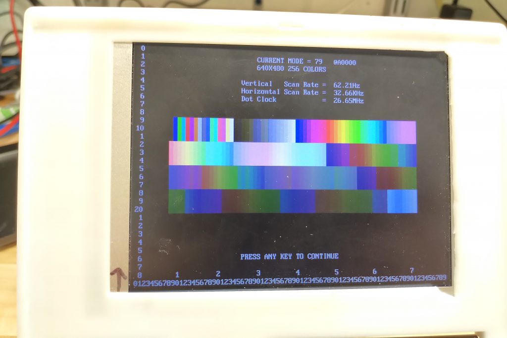
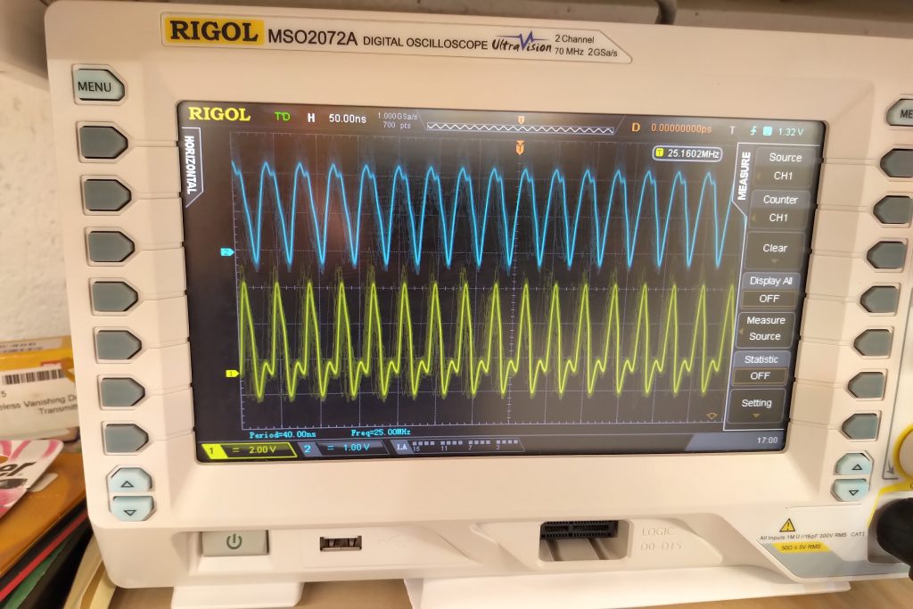
I continue to chase the goal of being able to drive the replacement display at the full VGA clock speed of 25.175MHz / ~60hz refresh rate.
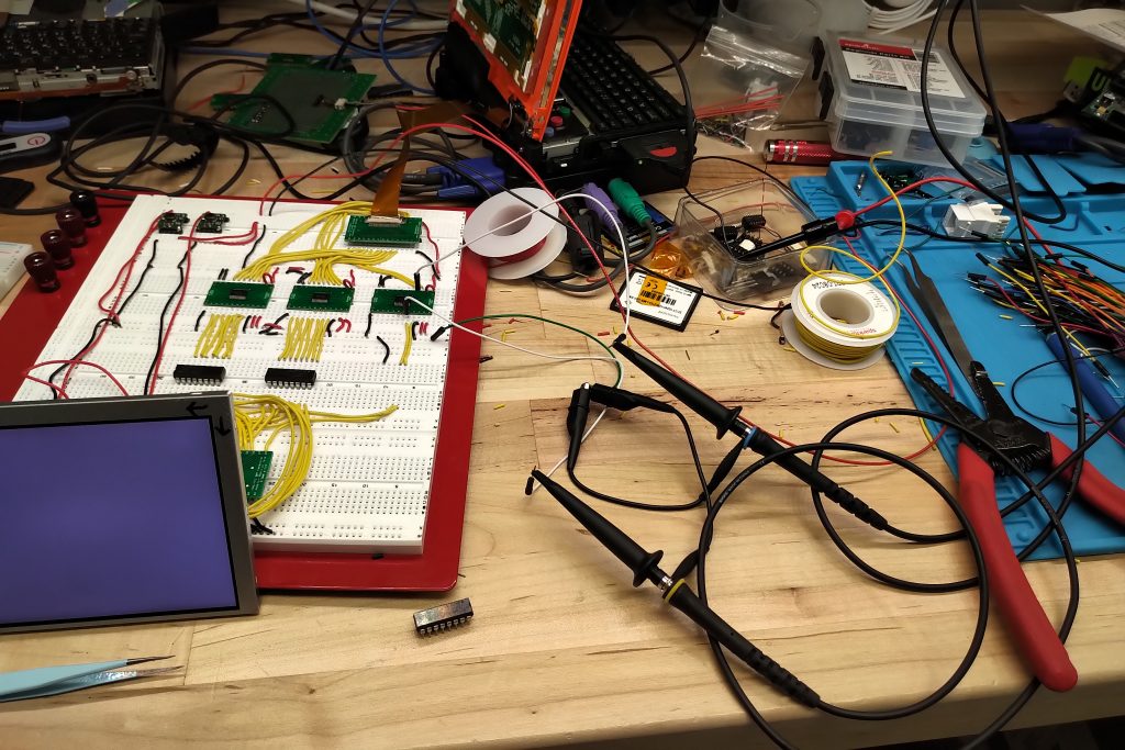
To summarize the issues I have been facing, in various versions of the PCB’s and hand wiring there was noise, jitter and other timing issues visible when certain patterns were displayed on the screen. The effect was not as bad when running at 15MHz but still there. It was terrible with sloppy handmade boards and breadboard testing.
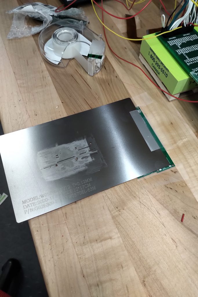
I attempted to fix this with various forms of shielding, however it became clear the the issue was not external noise, and the reason the the metal back plate improved the situation was due to some kind of inductive coupling or similar effect on the ribbon cable.
I concluded the issue was related to an impedance mismatch causing reflections of the signal. I looked at what type of source termination and receiver end termination may have been in place.
I found that all signals including the clock appear to have a 0ohm resistor between the CT65535 output pin and the FPC connector, and they are each coupled to ground with a 50pf or so capacitor. On receiving side they went straight into a Hitatchi HD151015 9 bit Level Shifter / Transceiver.
I figured these values and topology were designed based on the length of the path from the CT65535 through to the CSTN at the original clock speed (~8mhz if i recall).
Of course this is no longer the case with the adapter board where two new connectors are introduced, the traces on the adapter PCB, the ribbon cable on the AT050TN23v1 and then the difference of the input gates/etc on the TFT.
I had various attempts at implementing signal termination at the converter PCB and on the TFT DCLK pin itself with varying success but nothing repeatable. What would work with test leads would not work once soldered on. What worked in one orientation would not work in another it was all random. I believe this may have at least in part been related to trying to terminate in the middle of the transmission line and not close enough to the end.
It had also been observed that lowering the voltage of VCC on the TFT could improve the issue slightly, this was not practical but got me thinking about level converters to address the flight difference the PC110 ~3.5V and the 3.3V of the DC-DC. I also knew that the immediate input on the OEM display was a Hitatchi level converter.
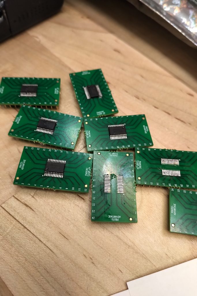
I purchased every possible level converter I could find on digikey, and generally the results were identical to it not being used at all. I then tried harvesting the Hitatchi level converters off an old CSTN and suddenly the signal was drastically improved, but still had some issues which I assumed was related to the hand wiring used for testing
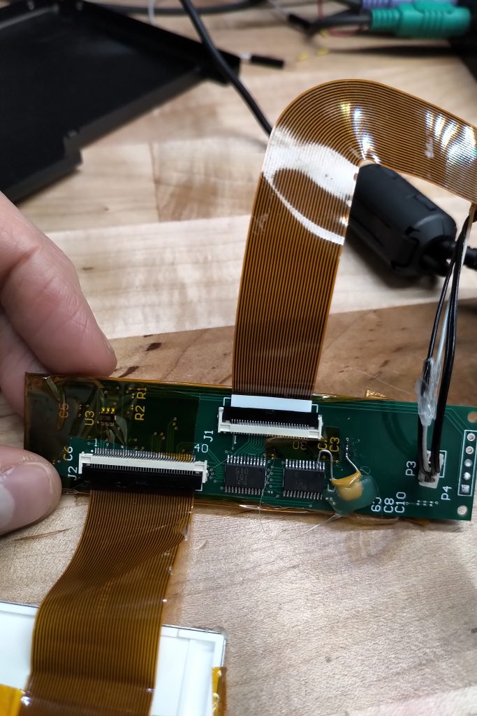
I produced a PCB to properly mount the Hitachi chips and upon initial testing there was almost identical issues with the signal/display as without the Hitachi chips. This was starting to solidify a sense of defeat.
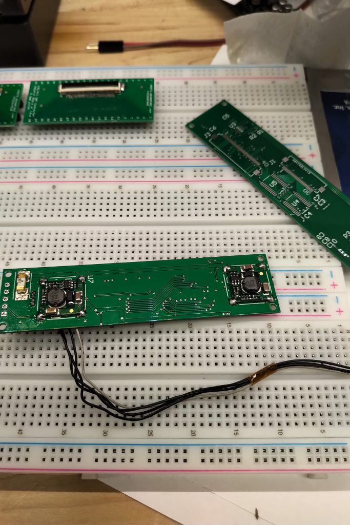
Due to missing (still missing) digikey delivery I was without the various capacitors to mount on the board, so there was still a small hope that the bypass capacitors on the level converters could help but not likely.
I then thought again if the previously attempted termination methods that failed would now have better luck given the long transmission line from the PC110 was now being terminated into the Hitatchi chip. Magically now, coupling the clock signal to ground with a 100nF capacitor at the input to the Hitatchi made the signal essentially perfect. Although I have not found issues yet, I expect there may be test images that result in some individual signal lines approaching clock speed and can benefit from the same filtering. Now I understand the issue is more about the speed of the transmission and not the frequency itself, but in practice it seems to be related to the frequency in this case.
I am going to order another revision of the PCB that will place 100nF capacitors as close to the Hitachi pins as possible. It is possible this approach may work with other actively available level converters but given the low volume of this project harvesting hitatchi chips from old displays and/or purchasing some limited qty of new old stock is good enough. It is also nice that the Hitachi chip has 9 channels allowing to accomplish the task with two chips, whereas most of the new parts are only 8 channel. The board is tight and my routing skills are limited.
Again in closing, I believe this all falls within “transmission line theory”, and with proper understanding it may be possible to simply place series resistors and/or capacitors on the converter board and with a correct value and solve the problem with less components i.e. no converters.
I am however taking the route of using the level converter chips to deal with the fact there is a difference between the Vcc from the 3.3V DC-DC and the “3.3V” on the PC110 motherboard. Putting the capacitors on the signal lines should create an RC filter, but I am not putting a resistor as I am assuming (from experimental testing) that the resistance of the trace/gate/etc is acceptable.
I am following with great interest. I have 5 of these devices, but only 1 LCD screen works. All the devices work via external VGA though. I have a 3D printer too, when you do figure out the screen to use and want to sell the adapter boards let me know. Keep up the great work, you’ve got a lot further than most people at cracking this.