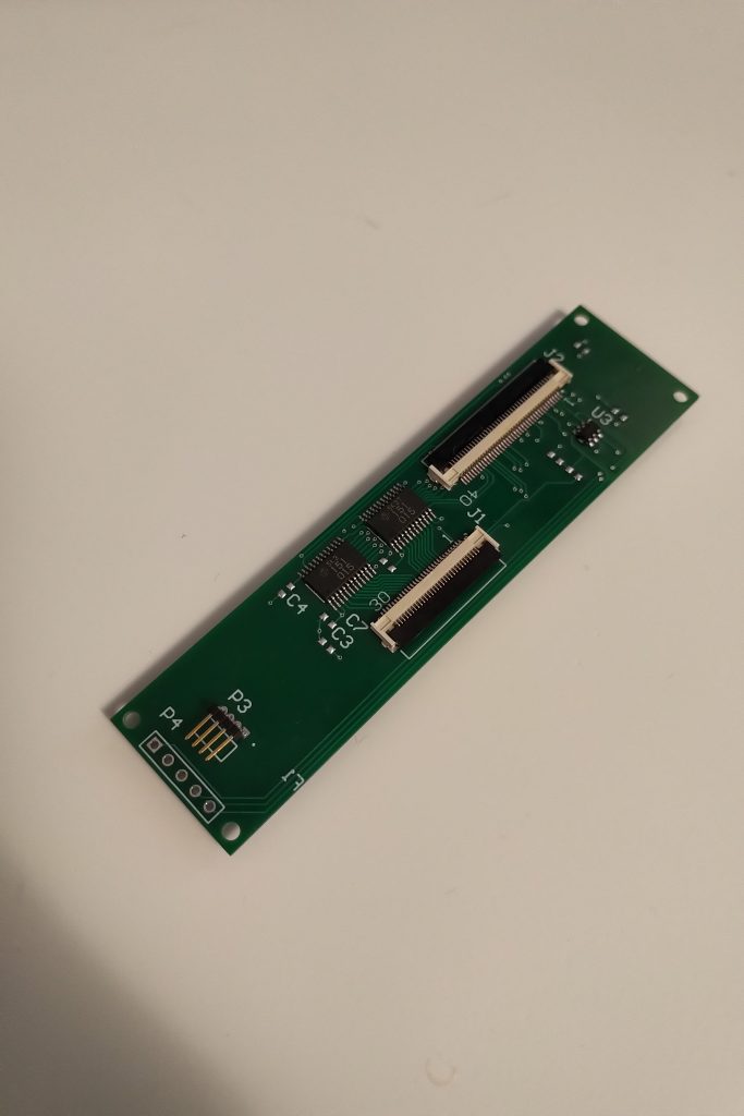
The issue I described as “blue tint” turns out to have been a fault in my test system. I built another revision of the PCB including pads for capacitors, and it would seem I only needed to place a cap on the clock line to resolve the remaining signal integrity issues.
Current Status
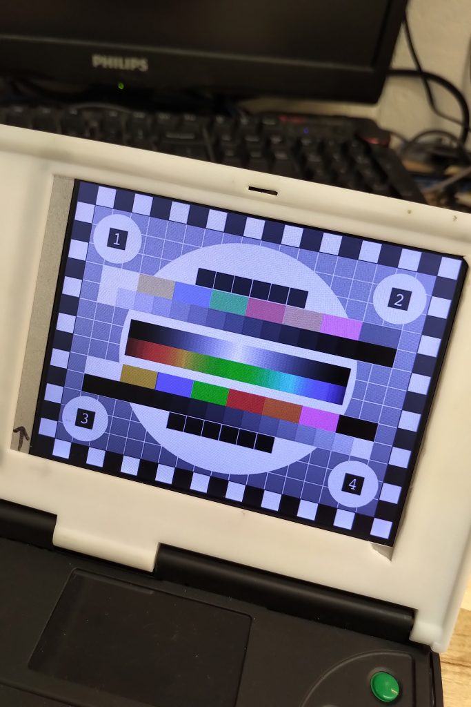
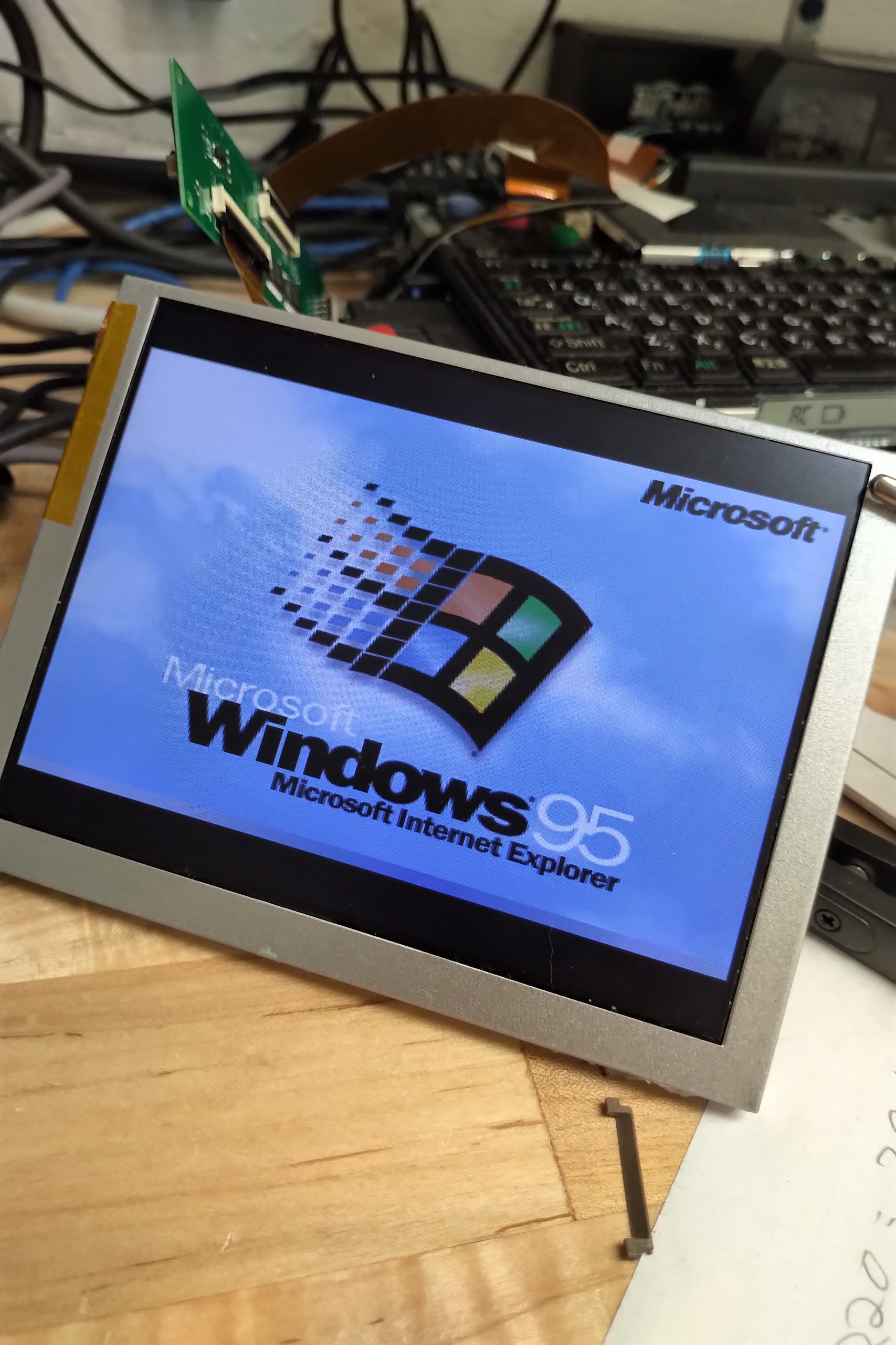
- Full VGA Clock (25.175MHz) without any pixel errors / artifacts
- Full brightness control via the contrast keys
- Less than 100µA draw on the 10.5V inverter supply while display is off.
- All electrical load is on the inverter supply wires and not the fpc.
- 250mA fuse to reduce risk of blowing the internal 650mA fuse in any unexpected failure modes.
- Using the Hitachi transceivers maintains same electrical interface to the CT65535 as the OEM display. This may be an overkill step but it is working well so I am sticking with it.
Next Steps
- Further verify there are no pixel errors at the higher clock speed.
- Revise the PCB to simplify assembly and clean it up.
- Update the 3d model for the new bezel to accommodate the new PCB.


Hi
You’re doing some amazing work! As an avid PC110 fan with a perfect example but with a unusable screen I’m really wowed by your work. Have you considered getting to a stage where you’re able to sell the kits? I think you’d be doing the community a service as well as funding future projects!
All the best, from the UK!
Alex
I’m with Alex on this Kevin, you’ve done some fantastic work 🙂
Just read the latest updates. It’s all looking great and the lights for the keyboard are just good fun 🙂
Fantastic work!! Any chance you’d consider selling your boards?
Would you consider releasing the PCB files under a license to allow experimenters to make some?