If you are looking to reserve a card in the upcoming batch see here: https://www.yyzkevin.com/picopcmcia/reservation/
I selected the 18pin HRS connector as in the end it was the best way to get as many signals out of the card in such a small space, as we need the rest of the card edge for the SDCard and Antenna.
I had planned to include various cables with each card, but reality set in once I got quotes on custom cable assembly in low volumes.
I will provide some cable choices as options for an added cost. I will also offer the unsoldered connectors for those who wish to make their own cables, I will buy a bunch at once so it will be a bit cheaper than you buying your own from Digi-Key/Mouser and will save on shipping.
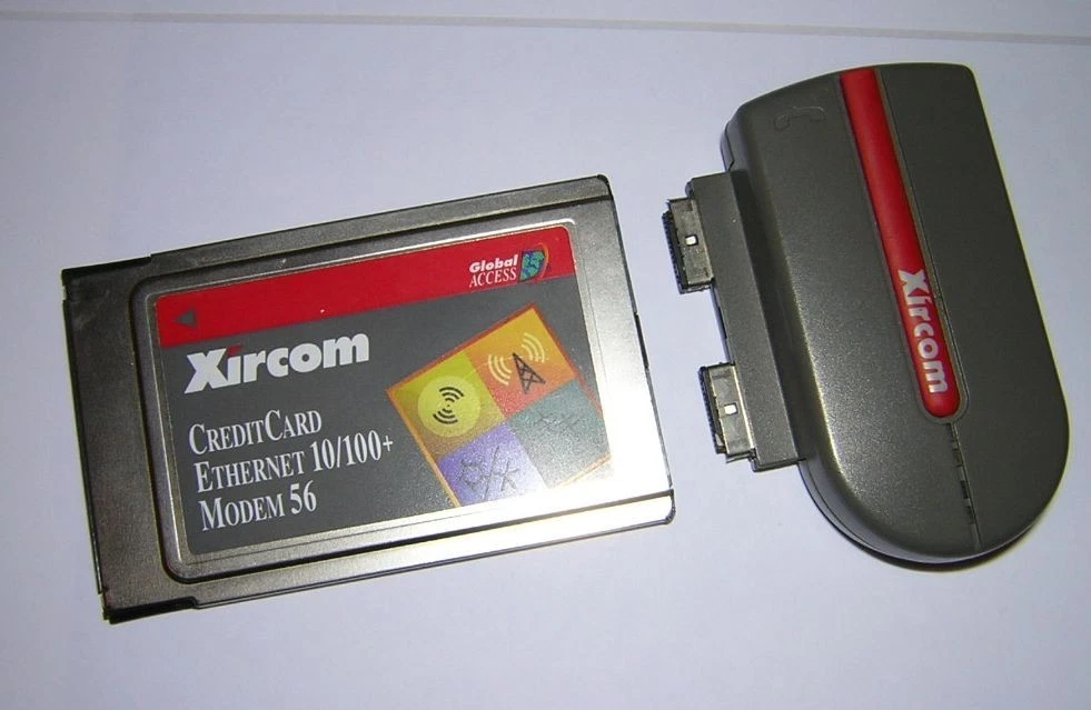
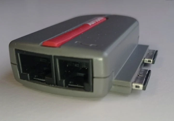
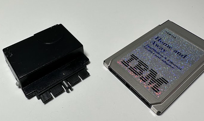
While contemplating this cost issue Kaede mentioned interest in making a PCB breakout board for development and it reminded me of these IBM/Xircom “rigid” dongles, which is the answer to the problem. A simple breakout board can be assembled much cheaper than a hand soldered cable and can provide all the basic features needed.
I’ve placed the Breakout into its own repository and I am working out the final details on it. Any feedback on features you would like to be included on this breakout would be appreciated.
Limitations / Constraints
- Must not be wider that 14mm from the center of the connector on the right hand side to ensure it can fit onto cards in some confined spaces.
- Can go wider on the left side but will obstruct the MicroSD. This should be okay as it is not intended to be hot swap.
- Want to keep the size as small as possible for convenience but also to minimize leverage and damaging the connector.
Planned Connections
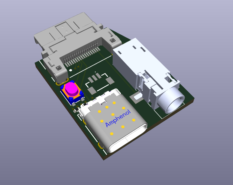
- USB-C (For programming and OTG peripherals)
- BOOTSEL Button (For programming)
- 3.5mm Headphone Jack (Amplified)
- 3pin JST-SH for RP2354 SWD
- 2.5mm MIDI OUT (not added yet)
If the budget can permit, a 3D printed clamshell to give it a finished look will be nice.
Example Rendering
Current Pinout
Pinout
| Pin | Signal | Notes |
|---|---|---|
| 1 | SWCLK | RP2354 Serial Wire Debug (SWD) |
| 2 | SWDIO | RP2354 Serial Wire Debug (SWD) |
| 3 | GPIO34 | User I/O: GPIO, UART0 TX, or I²C1 SDA |
| 4 | GPIO35 | User I/O: GPIO, UART0 RX, or I²C1 SCL |
| 5 | USB D− | RP2354 USB Port |
| 6 | USB D+ | RP2354 USB Port |
| 7 | BOOTSEL | Boot select (firmware flashing / recovery) |
| 8 | 5V | 5 V from PC bus (350 mA fused) |
| 9 | GND | Ground |
| 10 | I2C0 SDA | I²C master (onboard DSP + external peripherals) |
| 11 | I2C0 SCL | I²C master (onboard DSP + external peripherals) |
| 12 | — | Not connected (Yet) |
| 13 | GPIO26 | UART1 TX (also internally connected to SAM2695 MIDI RX) |
| 14 | IN1_L | Line-in left (to DSP) |
| 15 | IN1_R | Line-in right (to DSP) |
| 16 | HPL | Headphones out left (from DSP) |
| 17 | HPR | Headphones out right (from DSP) |
| 18 | GND | Ground |
Connectors
The PicoPCMCIA External I/O uses Hirose ST-series connectors, chosen for their compact size and robust locking mechanism.
🔗 Hirose ST Series:
https://www.hirose.com/en/product/series/ST
Connector Part Numbers
| Description | Part Number |
|---|---|
| Card Receptacle | ST60-18P(30) |
| Breakout Plug | ST60X-18S(30) |
| Cable Plug Assembly | ST40X-18S-CV(30) |
| Cable Bushing | ST40X-BS(4.0) |
| Cable Clamp (4 mm) | ST40X-CM |